Machining vibration can turn a precise production run into a costly correction. Chatter leaves visible waves on a milled wall, damages tool edges, and may shorten spindle life. In China’s diverse manufacturing sector, these problems appear in automotive parts, aerospace components, molds, and general metalworking.
This guide examines China’s top 10 ways to reduce vibration in machining. It explains how to reduce vibration in machining processes through practical controls, not vague promises. The discussion covers tool overhang, workholding stiffness, spindle condition, cutting speed, feed rate, depth of cut, and coolant delivery. It also considers machine foundation quality and modern vibration monitoring. A shorter tool may outperform an expensive tool. Small details matter.
Real workshop experience shows that vibration rarely has one cause. A loose fixture, worn insert, or unsuitable spindle speed can create similar marks. Engineers should inspect the machine, tool, material, and setup together. Sound changes can help, but measurement is more reliable. Accelerometers, spindle-load data, and test cuts provide stronger evidence. Still, no checklist fits every machine. That is worth remembering.
Some recommendations may need adjustment after testing. A speed chart can suggest a stable range, yet the actual workpiece may respond differently. Experienced machinists often change one variable at a time and record the result. This approach takes longer, but it prevents guesswork. The following methods combine established machining principles with practical observations from demanding production environments. They aim to improve surface finish, tool life, dimensional accuracy, and process confidence.
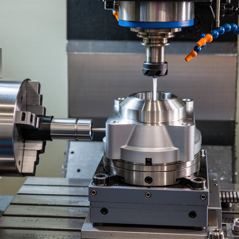
Vibration in machining is unwanted movement between the cutting tool, workpiece, and machine structure. It often creates a loud, uneven cutting sound. The finished surface may show regular waves or visible chatter marks. In daily workshop experience, unstable clamping is one of the easiest causes to miss. A thin plate can flex under cutting pressure. A long tool can also bend and vibrate, especially during deep pockets or narrow slots.
Cutting conditions matter greatly. Excessive cutting speed may excite the natural frequency of the setup. Too much feed can overload the tool edge. A worn, damaged, or incorrectly positioned tool increases cutting force. Runout in the holder or spindle creates uneven tool engagement. Even a sharp tool can vibrate when its overhang is unnecessarily long. These causes often overlap. That complicates diagnosis.
Start by checking the setup, not only the machine settings. Tighten the workholding system and support flexible areas. Reduce tool overhang whenever possible. Inspect tool runout with a suitable gauge. Listen to the cutting sound, then examine the surface pattern. A trial cut at lower speed can reveal whether resonance is involved. However, slower cutting is not always better. I have seen vibration increase after an unsuitable speed change. Measurement helps prevent guesswork, although basic observations still provide valuable clues.
It creates unwanted movement between the tool, workpiece, and machine structure. The cut may sound loud and uneven. Finished surfaces can show regular waves or chatter marks.
Loose workholding allows the part to move under cutting pressure. A thin plate may flex visibly. Tighten the fixture and support flexible areas. Small clues matter.
A long tool bends more easily during deep pockets or narrow slots. Reduce the overhang whenever possible. Even a sharp tool may vibrate when it extends too far.
Excessive speed can excite the setup’s natural frequency. Excessive feed can overload the cutting edge. Try a lower-speed trial cut, but slower is not always better. That needs checking.
Inspect the tool, holder, and spindle with a suitable gauge. A worn, damaged, or incorrectly positioned tool increases cutting force. Runout creates uneven tool engagement. Visual inspection alone can miss it.
Coolant reduces heat, friction, and chip recutting when directed at the cutting zone. It rarely solves chatter by itself. Check concentration, temperature, and nozzle position. Blocked nozzles can suddenly roughen a stable cut.
Tighten workholding and support thin parts with suitable fixtures. Reduce tool overhang and use a stable machine foundation. A tuned damper may help at difficult spindle speeds. The whole system matters.
Accelerometers, spindle-load signals, and acoustic sensors can detect changes early. Record a stable baseline first. Compare later readings with practical alarm limits. Sensors can mislead when mounted poorly or exposed to coolant noise.
Compare vibration data with tool wear, cutting depth, and chip shape. Listen to the cutting sound and inspect surface patterns. Measurement reduces guesswork, but it is not foolproof. Sometimes the monitoring setup needs adjustment instead.
Machining vibration, often called chatter, can reduce surface quality, shorten tool life, create dimensional errors, and increase noise. To understand how to reduce vibration in machining processes, operators should first identify its causes, such as excessive tool overhang, unstable workholding, unsuitable cutting conditions, weak machine structures, or improper tool geometry. Selecting rigid tools with suitable angles, minimizing projection length, and using sharp, balanced cutting edges can significantly improve cutting stability.
Vibration can also be controlled by optimizing cutting speed, feed rate, and depth of cut according to the material and machining operation. Secure workpiece clamping and a stable machine setup are equally important. In addition, appropriate coolant can reduce heat and friction, while damping supports or vibration-absorbing holders may help control resonance. Real-time monitoring of sound, force, and spindle behavior allows operators to detect unstable conditions early and make timely adjustments, improving efficiency, tool life, and final part quality.

 DSCUT CNC