Tool life directly affects machining cost, part quality, and production stability. A worn insert can leave rough surfaces, burrs, dimensional errors, or unexpected scrap. Small changes matter. A stable cutting process often begins with correct speeds, feeds, coolant delivery, and tool selection.
This guide explains how to increase tool life in machining operations through seven practical methods. These methods include controlling cutting conditions, reducing tool runout, improving workholding, and selecting suitable coatings. Regular inspection also matters. A carbide insert with chipped edges should not remain in service. Replace it before damage spreads to the workpiece or holder.
Real shop-floor results depend on the material, machine condition, and operator judgment. Aluminum, stainless steel, hardened steel, and titanium each create different wear patterns. Heat may discolor a tool, while built-up edge can distort cutting performance. Coolant helps, but it cannot correct an unsuitable feed rate or poor chip evacuation. That assumption can fail.
No process is perfect.
Experienced machinists often adjust parameters gradually instead of trusting a catalog value blindly. They monitor spindle load, vibration, chip shape, and surface finish during production. Tool-life records can reveal patterns that memory misses. One useful lesson is easy to overlook: longer tool life is not always the main goal. Predictable tool life may be more valuable than one exceptional cutting cycle. The following seven approaches connect technical settings with daily maintenance, measurement, and disciplined process control.
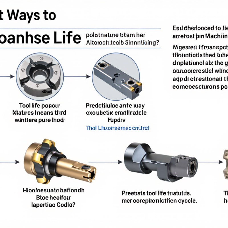
Tool life depends on more than the cutter’s material. Cutting speed, feed per tooth, and depth of cut create the main thermal and mechanical loads. Excessive speed often causes flank wear, while an aggressive feed can chip the cutting edge. These settings interact. A stable combination usually outlasts a higher-performance setting pushed too far.
Machine rigidity also matters. Vibration leaves repeated marks on the workpiece and weakens the tool edge. Check clamping, tool projection, spindle condition, and workholding before changing cutting data. Shorter projection helps. Coolant must reach the cutting zone consistently, especially during interrupted cuts. Poor chip evacuation can recut hot chips and accelerate crater wear. I have seen a clean-looking setup fail because chips collected around the cutter.
Tool geometry should match the material and operation. A sharp edge may cut aluminum smoothly but fail quickly in hardened steel. Choose suitable rake, clearance, and edge preparation. Inspect the tool under magnification when possible. Record cutting time, surface finish, spindle load, and wear location. This makes replacement more predictable. Do not rely only on sound; operators sometimes accept gradual noise changes. I still review these records because one unexplained failure can expose an overlooked coolant, alignment, or programming problem. Temperature, rigidity, and chip control deserve equal attention.
7 Best Ways to Increase Tool Life in Machining?
Select Tool Materials, Coatings, and Geometries for the Job
Tool life begins with the workpiece, not the cutting tool. Match carbide grades to hardness, toughness, and interrupted cutting conditions. Use ceramic tools for stable, high-temperature machining of suitable hardened materials. Choose polycrystalline diamond for abrasive nonferrous alloys, while cubic boron nitride suits many hardened steels. The wrong substrate can fail within seconds. It happens.
Coatings should support the actual cutting environment. A heat-resistant coating can protect tools during dry or high-speed cutting. A low-friction coating may reduce built-up edge when machining aluminum or other sticky alloys. However, coating choice cannot repair poor setup conditions. Excessive heat, weak clamping, or poor chip evacuation will still shorten tool life. Keep coolant directed at the cutting zone, when the tool and material allow it.
Geometry needs equal attention. A positive rake angle reduces cutting force but may weaken the edge. A stronger edge preparation handles interrupted cuts better. Select flute count, helix angle, nose radius, and clearance for the operation. For example, a large nose radius can improve finish, yet it may increase vibration on a flexible component. Reduce radial engagement when chatter appears. Check the chips, edge color, and wear land after each trial. Tool-life charts help, but they are not final answers. Actual results depend on machine rigidity, toolholding, material variation, and operator judgment. A short, documented test is often more reliable than an attractive specification sheet.
7 Best Ways to Increase Tool Life in Machining?
Cutting speed usually controls tool wear most aggressively. The Machining Data Handbook lists typical Taylor exponents of about 0.20 to 0.30 for carbide turning. This means a 10% speed reduction can extend tool life by roughly 40% to 60%. The exact result depends on material, coating, coolant, and rigidity. Start conservatively, then increase speed in small steps.
Feed rate needs equal attention. Excessive feed creates higher cutting forces and edge chipping. Too little feed can cause rubbing, heat, and built-up edge. Use the cutting tool maker’s recommended feed range, but verify it with actual chips and flank wear. A continuous, curled chip is healthier than a blue, fragmented one. ISO 3685 tool-life testing also emphasizes consistent cutting conditions, which many shops overlook.
Depth of cut should match the insert’s edge preparation and machine stability. A shallow pass may repeatedly contact the worn surface, while an unstable deep pass can overload the insert. Leave enough material for a firm finishing cut. Record speed, feed, depth, cycle time, and wear after each test. I once treated feed as the main problem, but the real cause was excessive speed and poor workholding. Small corrections beat dramatic parameter changes.
Optimize cutting speed, feed rate, depth of cut, tool selection, cooling, setup rigidity, and chip control.
The chart shows a normalized tool-life estimate when cutting speed changes from a baseline value. It uses the Taylor tool-life relationship, T × Vn = C, with n = 0.25 as a representative carbide-tool exponent. Reducing cutting speed generally increases tool life, while excessive feed rate, depth of cut, heat, vibration, and poor chip evacuation can accelerate wear. Actual results depend on the workpiece, tool material, coating, machine rigidity, coolant, and cutting conditions.
7 Best Ways to Increase Tool Life in Machining?
Control Coolant, Chip Evacuation, and Cutting Temperature
In machining, tool life often falls before the cutting edge looks damaged. I have seen a fresh insert fail after one interrupted cut because coolant arrived late. Control begins with a stable, correctly aimed flow. Direct the stream at the cutting zone, not the tool holder. Use enough pressure to break the heat barrier and wash chips away. Flood coolant helps many operations, but it is not automatically better. On some cuts, poor delivery creates thermal shock and edge chipping. Check the nozzle after every setup change.
Chip evacuation deserves equal attention. A chip trapped in a deep pocket can recut against the flank and raise cutting temperature within seconds. Keep coolant moving through the cavity, and use tool paths that open a clear escape route. Adjust feed, stepdown, or pecking when chips appear blue, curl tightly, or pack around the tool. Short pauses may help, but they can also rub the edge. Watch the sound and chip shape, not only the machine display. A clean chip is useful evidence.
Temperature control requires measurement and judgment. A handheld infrared check can mislead because shiny surfaces reflect heat. Compare tool wear, chip color, and spindle load together. Reduce cutting speed when heat remains concentrated at the edge. Increase feed carefully if rubbing is the real problem. I once lowered speed too far and shortened tool life through excessive contact time. That mistake still matters. Record coolant concentration, nozzle position, material, and wear after each trial. Small records reveal patterns that memory misses.
| No. | Tool-Life Improvement Method | Key Variable to Control | Practical Starting Guideline | What to Monitor | Typical Benefit |
|---|---|---|---|---|---|
| 1 | Maintain the Correct Coolant Concentration | Refractometer concentration | Use the fluid manufacturer’s specified range. For many water-miscible metalworking fluids, general machining commonly starts around 5–10% concentration. | Refractometer reading, odor, foam, corrosion, residue, and skin irritation | Improves lubrication and corrosion protection while reducing excessive foam and premature fluid degradation. |
| 2 | Deliver Coolant Directly to the Cutting Zone | Flow direction, pressure, and access | Position the nozzle so coolant reaches the tool–workpiece interface rather than merely flooding the outside of the tool. Through-tool or high-pressure delivery is especially useful for deep holes and narrow slots. | Visible coolant coverage, smoke, built-up edge, chip color, and temperature trend | Reduces thermal shock, friction, built-up edge, and heat-related wear when the fluid reaches the active cutting edge. |
| 3 | Improve Chip Evacuation | Chip packing, flute clearance, and coolant flushing | Use an appropriate peck cycle for deep drilling, withdraw the tool often enough to clear chips, and avoid recutting chips in pockets, grooves, and deep cavities. | Chip nesting, scratched surfaces, rising spindle load, flute damage, and sudden tool breakage | Prevents chip recutting, edge chipping, flute clogging, and localized heat accumulation. |
| 4 | Control Cutting Temperature | Cutting speed, heat removal, and intermittent engagement | Begin with the cutting-tool supplier’s recommended speed range. If flank wear accelerates rapidly, reduce cutting speed in small steps and improve coolant access before making large parameter changes. | Tool discoloration, workpiece discoloration, thermal cracks, flank wear rate, and infrared temperature trend | Limits diffusion, oxidation, softening, and thermal cracking of the cutting edge. |
| 5 | Use Stable Cutting Parameters | Cutting speed, feed per tooth, and depth of cut | Keep feed per tooth high enough to produce a controlled chip, but stay within the tool and machine limits. Avoid sudden changes in engagement, excessive radial load, and rubbing conditions. | Spindle load, vibration, chip thickness, surface finish, and edge chipping | Reduces rubbing, chatter, mechanical shock, and uneven wear along the cutting edge. |
| 6 | Prevent Vibration and Tool Deflection | Tool overhang, workholding rigidity, and runout | Use the shortest practical tool overhang, secure the workpiece firmly, and verify tool runout before machining. For long-reach tools, reduce cutting load and use suitable support or tool geometry. | Chatter marks, acoustic changes, poor surface finish, uneven edge wear, and dimensional variation | Protects the cutting edge from intermittent impact and reduces uneven flank and corner wear. |
| 7 | Inspect and Replace Tools by Wear Limit | Flank wear, crater wear, edge chipping, and process capability | Set a repeatable replacement limit based on tool geometry, surface finish, dimensional tolerance, and part material. Do not wait for catastrophic breakage or unacceptable parts. | Flank-wear width, cutting force, spindle load, surface roughness, burr formation, and part size | Prevents secondary damage, unpredictable tool failure, scrap, and excessive cutting forces. |
Reliable tool life begins with machine maintenance, not only cutting parameters. Inspect spindle runout, holders, lubrication points, and coolant flow before production starts. A dirty filter or loose holder can create vibration, uneven wear, and poor surface finish. In practice, small alignment problems often become expensive tool failures. I once saw a cutter fail early because coolant reached one side of the tool poorly. The setup looked acceptable, but the wear pattern told a different story.
Monitor tools during every production run. Track cutting time, part count, spindle load, vibration, and surface quality. Replace a tool before its edge breaks, especially when machining hard materials or tight-tolerance parts. Visual checks should include flank wear, chipping, built-up material, and unusual color changes. Use measured wear limits instead of relying only on sound or operator instinct. Records also help reveal repeated problems, although imperfect data can still mislead decisions. Review it with actual inspection results.
Tips: Clean holders daily. Check runout regularly. Keep coolant consistent. Mark replacement limits clearly. Train operators to report unusual noise immediately. Do not stretch tool life blindly; a cheaper replacement can prevent scrapped parts, damaged fixtures, and unplanned downtime.
Match carbide grades to hardness, toughness, and interrupted cutting. Ceramic suits stable, high-temperature machining of suitable hardened materials. The wrong substrate can fail within seconds.
Heat-resistant coatings help during dry or high-speed cutting. Low-friction coatings can reduce built-up edge on aluminum and sticky alloys. Coatings cannot fix weak clamping or poor chip evacuation.
A positive rake angle lowers cutting force but may weaken the edge. Stronger edge preparation handles interrupted cuts more reliably. Choose flute count, helix angle, nose radius, and clearance carefully.
Reduce radial engagement and inspect the setup. A large nose radius may improve finish but increase vibration on flexible parts. The real cause may be toolholding, rigidity, or excessive cutting load.
Reduce cutting speed conservatively before changing several settings. A 10% speed reduction may significantly extend carbide tool life. Increase speed gradually after checking chips and flank wear.
A continuous, curled chip usually indicates stable cutting. Blue or fragmented chips suggest excessive heat or inconsistent conditions. I once blamed feed, but speed and workholding caused the problem.
Inspect spindle runout, holders, lubrication points, and coolant flow. Clean holders daily. A dirty filter or loose holder can create vibration and uneven wear.
Replace it before edge breakage, especially during hard machining or tight-tolerance work. Track cutting time, part count, spindle load, vibration, and surface quality. Do not stretch tool life blindly.
Increasing tool life in machining operations begins with understanding the conditions that cause cutting tools to wear, including cutting forces, material hardness, heat, vibration, and interrupted cuts. A practical approach to how to increase tool life in machining operations is to match the tool material, coating, and geometry to the workpiece and cutting application. Proper rake angles, edge preparation, and tool rigidity can reduce friction and prevent premature chipping.
Process settings are equally important. Optimize cutting speed, feed rate, and depth of cut to balance productivity with manageable heat and cutting forces. Apply coolant consistently when appropriate, and ensure chips are evacuated effectively to prevent recutting and heat buildup. Regular machine maintenance, accurate tool alignment, and stable workholding also help maintain predictable performance. Finally, monitor tool wear through inspections, sound, surface finish, and cutting load, then replace tools before failure affects quality or damages the workpiece.

DSCUT CNC